


Kohlman Rabbani, E. R
Departamento de Engenharia Civil / Escola Politécnica – Universidade de Pernambuco / Praça do Internacional, 455, Pernambuco, Brasil+55 (81) 2119-3855 / emilialsht@upe.poli.brBarkokébas Jr., BDepartamento de Engenharia Civil / Escola Politécnica – Universidade de Pernambuco / Praça do Internacional, 455, Pernambuco, Brasil+55 (81) 2119-3855 / bedalsht@upe.poli.brLago, E. M. GDepartamento de Engenharia Civil / Escola Politécnica – Universidade de Pernambuco / Praça do Internacional, 455, Pernambuco, Brasil+55 (81) 2119-3855 / elianelsht@upe.poli.br
Véras, J. C
Departamento de Engenharia Civil / Escola Politécnica – Universidade de Pernambuco / Praça do Internacional, 455, Pernambuco, Brasil+55 (81) 2119-3855 / julianalsht@upe.poli.brSouza, S. S. BDepartamento de Engenharia Civil / Escola Politécnica – Universidade de Pernambuco / Praça do Internacional, 455, Pernambuco, Brasil+55 (81) 2119-3855 / bbouwman@hotlink.com.brAlmeida Filho, R. P.Departamento de Engenharia Civil / Escola Politécnica – Universidade de Pernambuco / Praça do Internacional, 455, Pernambuco, Brasil+55 (81) 2119-3855 / raimundolsht@upe.poli.br
ABSTRACT
ABSTRACT
Electrical energy can change in an instant from a silent assistant at work and provider of well-being and comfort into a mortal danger, and it is a change that is occurring with alarming frequency. In order to perform satisfactorily and be sufficiently protected against the hazard of fatal accidents, every electrical installation needs to have an adequately dimensioned grounding system. To characterize such systems at high-rise worksites in Pernambuco, Brazil, the research was performed at 66 sites sampled randomly among 47 construction firms between May 2006 and April 2007, analyzing the conditions and compliance with current norms of their electrical installations and grounding systems. Direct connection to the ground was utilized at 97% of the observed sites, while the remaining 3% possessed common point grounds. At the majority (74%) of sites, machine and equipment casings were grounded, with adequate electrodes being used in 97% of them. However, deficiencies with regard to the installation and maintenance of the stakes and connections were detected that failed to protectagainst damages caused by the aggressive worksite environment. It was verified that 88% of the stakes were installed in wet areas or in areas with frequent worker traffic or permanence. Beyond this, 86% of the worksites did not possess grounding resistance measurement reports. The research results showed that while companies, especially those of larger size, are investing in electrical installations and adequate protection systems, there are still grave problems in the manner of installation and utilization of such systems and in the availability of required documentation. This proves that it is necessary to invest more in education and awareness for civil construction workers and management, not only about the equipment they must acquire, but on the manner in which it must be installed, documented and utilized.
Keywords
Keywords
Safety management in construction, Electrical hazards, Grounding system, Work safety
INTRODUCTION
INTRODUCTION
The risks of electric installations
It is impossible to imagine the present world without the electrical system, it is displayed in all the branches of professional activities but electrical energy has also as characteristic the potentiality of causing accidents. Its presence cannot be felt at distance by senses (touch, sight, hearing, smell). These non-controlled risks can cause accidents which vary from superficial injuries to fatal accidents.
The transition of electrical energy from a silent co- assistant and co-providerof well-being and comfort to a lethal hazard is a change that, still in these days, a lot of people don’t understand until the undesirable event electric shock takes place involving them. Therefore, for understanding the steps and safe procedures needed to the use of energy and the handling of electrical installations requires the comprehension of electrical risks [1].
The civil construction industry displays a multiplicity of factors whichpredispose the worker to accidental risks such as: unfitted provisional facilities with electrical installations ill executed, sub-dimensioned and with ill maintenance or aging that create situation of risk either to the safety of gears or to the life of users [2]
According to Ore & Casini apud Alencar et al [2], more than 2000 (twothousands) casualties by electrocution were identified among workers of civil construction in the United States, in the period between 1980 and 1991, with an annual average of 2.5 casualties for each group of a hundred workers. Albeit this ratio has diminished, the death of construction workers still would correspond to a ratio four times bigger than that of all industries put together, what justifies a corrective action to the problem. One observes that these numbers are evidenced in Brazil, according to SINDUSCON/PE apud Barkokébas et al [3] electric shock is responsible for only6.78% of accidents in civil construction in Pernambuco, being that when analyzing the fatal accidents in civil construction one verified that 50% are caused by electric shock. Inserted on this problem, electrical risks arising out of unfitted installations must be extricated or at least minimized at work sites.
The Brazilian norms predict specific protection systems to electricalinstallations, on what refers to the safety of the worker one can quote the Regulatory Norm n. 10 – NR 10 [4] which concerns the installations and services in electricity, that has come into force since December of 2004 and establishes the minimal conditions to the implementation of controlling measures and preventive systems in electrical installations, in addition to the protection against electric shock that must be guaranteed by the application of protection measures against direct and indirect contacts. The NBR 5410 norm [5] establishes the guidelines to the dimensioning and installation of the equipotentialization systems. In addition to this norm recently came into force the law n.11,337 from July 2006) which aims thesafety of electrical installations and that makes it obligatory that all the buildings have a grounding system and electrical installations compatible with the use of ground conductor of protection, as well as, plugs with the third corresponding contact, beside this it predicts that electrical sets with metallic frames and sensible to abrupt variations of tension dispose of protection grounding conductor and respective tri-polar adaptation.
The study of case took place in the Metropolitan Region of Recife – MRR,which consists of an agglomerated formed by 14 municipalities interconnected and articulated by the urban spot that spreads from the capital of the state of Pernambuco, occupying 2,83% of the Pernambucan territory. This special ensemble corresponds to a long lane from North to South with a surface of 2,761 square kilometers, about 3% of the total area of the state, and with a demographic density of 1,206 inhabitants per square kilometer.
The population contingent of the Metropolitan Region of Recife is quiteirregular, with the concentration of 79% of the population in only four municipalities; Recife, Olinda, Jaboatão dos Guararapes and Paulista. With a Gross Domestic Product – GDP estimated in R$13.44 billions the metropolitan economy represents about 68% of the Pernambucan GDP. Civil construction participates with approximately 18% of the Gross Domestic Product – national GDP, being responsible for an expressive parcel of the Brazilian economy development. In the state of Pernambuco, civil construction yet participates with approximately 20% of the industrial GDP and 35% of jobs, and still highlighting itself by its social role, for it is an area which gives support to all others industrial activities. In the year of 2004 one would find registered in this sector of civil construction, 1,118,570 employees in all Brazilian territory, being 209,000 (18.84%) in the Northeast region; in the same year there were identified 96,604 enterprises acting in this sector, with 15,077 (16.23%) with headquarters in the Brazili9an Northeast.
Protection system against electric shock
Protections against electric shock
According to Cadick et al [1] electric shock is the physical manifestation that occurs when an electrical current flows through the human body. The symptoms may include from a slight sensation of tingling, to violent muscular contractions, cardiac Arrhythmia or damage to the tissues.
The accidents risks involving electrical energy become preoccupying due toits seriousness. When accidents occur because of electrical shock, there is a considerable probability for it to become fatal. This will depend mainly on the intensity of the intensity, frequency, time of duration and on the passage of the current through human body [2].
The safety aspects related to the installations of low tension, which include those of residential matrix, and that falls again into the scope of the NBR 5410, are clearly specified, for instance in the item 5, titled “Protection to Guarantee Safety”. When approaching the subject Protection against Electric Shock, such norm establishes two fundamental principles which are key-ring for the understanding of the rules, procedures and norms and, consequently, to the effectuation of the hazards control inherent to the handling, operation and intervention in electrical webs.
Principle 1: accessible dangerous alive parts do not have to be accessible and, Principle 2: accessible masses or conductive parts do not have to offer danger,either in normal conditions, or, in particular, in the case of any imperfection which may cause them to become accidentally alive.
Thus, the protection against electric shocks, still in accordance with NBR 5410 understands two lines of defense or two types of protection: a) the basic protection – mean aimed to hinder the contact with dangerous alive parts, such as: basic isolation, barrier, pack, limitation of tension, amongst others; b) supplementary protection - half destined to supply the protection against electric shocks when accessible mass or conductive parts becomes accidentally alive, such as: supplemental isolation, equi-potentialization and automatic sectioning of the feeding, amongst others.
In this way, NBR 5410 establishes as general rule for protection against electric shocks that the declared principles are assured at the very least, for the joint provisions of basic protection and supplementary protection. In the places or situations where the provisions of these last ones integrally does not assure the basic principles previously cited, the set will be added to the additional protection. It is important to notice that the supplementary protection, generally, it is become incorporated additional protection – mean aimed to guarantee protection against electric shocks in situations of bigger risk of loss or cancellation of the normally applicable measures, of difficulty in the full attendance of the security conditions associates the measured determined one of protection and/or, still, in situations or places where the hazards of electric shock are particularly serious [5].
Equi-potentialization of the electrical installations.
This measure of protection is destined to prevent that a contact tension of maintaining for a time which can result in risk of dangerous physiological effect for people or animals and, it is based on the performance of a device of automatic cut that detaches the defective installation when it will be able to circulate dangerous intensities through people or animals.
According to NBR 5410 [5], the prescriptions that translate the basic principles of the applied equi-potentialization to the protection against electric shocks are the following ones: 1) all the masses of an installation must be on the protection conductors; 2) in each construction a main equi-potentialization must be carried through, and as many equi-potentializations necessary; 3) all the situated masses of the installation in one same construction must be entailed to the main equi-potentialization of the construction and, in this manner, to one exactly and only grounding electrode, for ends of protection against shocks and/or electromagnetic compatibility; 4) masses protected against electric shocks for one exactly device, inside of the rules of protection for automatic sectioning of the feeding, must be entailed to one same grounding electrode; and 5) all circuit must make use of protection conductor, in all its extension
According to Mamede Filho [ 6 ], in order to function with a performance satisfactory enough and to be insured against risk of fatal accidents, all high- voltage electric installation and of low tension must adequately possess a system of dimensioned grounding for the conditions of each project. Soon, a grounding system aims at : a) the security of performance of the protection; b) protection of the installations against atmospheric discharges; c) protection of the individual against contacts with energized metallic parts of the installation accidentally; and
d) uniformization of the potential in all the area of the project, preventing against dangerous injuries that can appear during an imperfection phase-land.
The objective of the groundings is to assure without risk of danger the draining of currents of lack and escape for land, satisfying the necessities of security of the people and employees of the installations. According to Hélio Creder [ 7 ] in the electric installations two types of groundings are considered : the functionary (which consists of the earthen of one of the conductors of the system and it is related with the correct, safe and trustworthy functioning of the installation) and that of protection (which consists of the linking to land the masses and the strange conducting electrodes to the installation, aiming at to the protection against electric shocks for indirect contact. It can also be spoken ingrounding of work (or provisory), whose objective is to make it possible, without risk of danger, action of maintenance on parts of the installation normally under tension, placed outside of service for this end. The election and installation of the grounding components must be such that: a) the value of the gotten resistance of grounding does not have to be modified considerably along time; b)they resist to the thermal, thermo-mechanic or electromechanical requests; c) they are adequately robust or they possess protection mechanics appropriate to face the external conditions of influence.
Basic specifications for the grounding system.
Grounding basically possesses four components: the electric connections; the linking conductor; the grounding electrode and the land that involves the electrodes. As Hélio Creder [ 7 ] the installation of grounding mesh will have at the very least to be executed from specific project that will have to contain, at least:
• Blueprints• Schemes (enfilades and others that may be needed)• Setting details when necessary• Descriptive memorial• Specification of the components: succinct description of the component, nominal characteristics and norm that they shall attend to.
In a grounding system, it is considered as land resistance the effect of three resistances, knowing: i) the relative resistance to the existing connections between the land electrodes (connecting rods and handles); ii) the relative resistance to the contact between the land electrodes and the surface of the land that surrounds them; the relative resistance to the land in the immediacy of the land electrodes, called, also, of dispersion resistance. It fits to point out that the chain density is great in the surroundings of the land electrodes, where carried through inquiries show that 90% of the total electric resistance of the land that involves an electrode embedded in it generally inside of a ray of 1,8m 3,5m of the geometric axis of the proper electrode [6].
The bigger the length of the rod the less resistance of grounding, this because the bigger the connecting rod the bigger the surface the current passage, thus diminishing the resistance. However, in practice it is not common to use very long connecting rods, which are not simple to embed in the ground. The most used are of 2 and 3 m. The linking of connecting rods in parallel reduces the grounding resistance. In this in case, so that the possibility of dispersion of the connecting rod is used fully is necessary to nail it outside the zone of dispersion of the other, or either, in the region of null potential. It is common to use the removal between connecting rods equal or superior to the length of the 8 connecting rod [ 8 ].
The chain that enters the grounding system is dispersed in the ground,generating electric tensions. These tensions if applied to the human being, they provoke electric shocks being able to cause ventricular fibrillation. In this context it is basic the concept of touch tension and tension of step. The touch tension is the existing electric tension between the superior and inferior limbs of an individual, due to an imperfection in the equipment, while the step tension can be understood in the following way, considering an electrode of vertical grounding nailed into a homogeneous land, and its area of radial dispersion of until a meter one has a limited parcel of tension which a close person can be submitted to a tension called step. The step tension can provoke serious damages to a person due to the current levels and tension that can be attained [9].
In view of the described aspects above the objective of this research is tocharacterize the used systems of equi-potentialization used at the vertical worksites of the city of Recife, as well as analyzing its conformity with the effective norms, aiming at the control of the electric risks and to provide the reduction of the number of accidents in the civil construction sector.
THE METODOLOGY APPLIED TO THE RESERCH
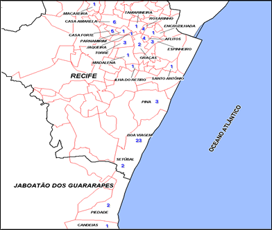
The study was carried through in a mistral universe determined in the Metropolitan Region of Recife - MRR. 66 work sites were chosen randomly amongst 47 different constructors who were registered in the database of the Union of the Civil Construction Industry of the State of Pernambuco - Sinduscon/PE, of 2006/2007 had been visited. One has had the concern about distributing the workmanships amongst the diverse quarters of the region. Figure 1 presents a space vision of the distribution of the used mistral space in the research
Figure 1 – Map of Recife and Jaboatão dos Guararapes with the distribution of the visited work sites
For identification of the electric risks at the work sites, a specific protocol, based in previous studies was elaborated and the current law (NR 10, NR 18 and NBR 5410). This instrument had as greater objective the identification of relative non-conformity to the electric installations that could generate danger to the user, the proper installation and the patrimony, especially as for the systems of protection against electric shocks. The collection of data in the work sites was carried through between May of 2006 the April of 2007. Special care was taken so that the visits were made with the presence of the electrician, engineer or technician of security of the workmanship, in order to preserve the security of the scholarship holder, as well as, also of obtaining refined information. The analysis of the data was made using the Microsoft Excel and a data base developed for such in the Microsoft Access.
ANALISYS OF THE RESULTS
The majority of the visited workmanships was found in the phase of structure and finishing, as it shows Table 1, as the provisory electric installations are installed in the beginning of the activities in the work site, there were realized that the constructors do not carry through a periodic maintenance in the installations, they are only modified in agreement with the necessities without the existence of a project adjusted for the respective adaptations.
|
Phase |
Quantity |
Percentual |
|
Foundation |
4 |
6 |
|
Structure |
21 |
32 |
|
Masonry |
16 |
24 |
|
Finishing |
25 |
38 |
|
Total |
66 |
100 |
|
Source: Field research |
Table 1 – Work phases
Some observed data had been positive, showing that it is being disposed in relation to the requirements of the norms. When evaluating the grounding in all the existing machines and equipment in the work site, it has been seen that the majority was in agreement (74%), having been found equipment without grounding in 17 work sites of the 66 visited workmanships. The great majority of the construction companies (97%) also had adequate lengths of groundings electrodes, or either between 2,0 m or 3,0 m and with minimum diameter of 15mm.
However some data are preoccupying for the great majority (86%) of thevisited workmanships did not have evidential finding of the resistance test of groundings. The great majority of the workmanships also did not have a project with an adequate sizing of the groundings, in view of that 95% of the workmanships had not presented updates enfilades projects of the electric installations with specification of the grounding system and devices of security ( see Table 2)
Results Agree%
Disagree%
Grounding of all equipment 74 26
Length of the electrode 97 3
Resistance of the grounding system 14 86
Unifilar schemes of the installations 5 95
Source: Field research
Table 2 – Grounding of gears, Length of the grounding electrode and grounding resistance.
When observed, the grounding system used in each equipment at the work site ( see Table 3), it was verified that almost all, a 97% total, used direct bonding with the land and 3% had slide bars of main equi-potentialization - BEP in its provisory electric installations
|
Results |
Quantity |
Percentual |
|
Direct plugging to land by electrode |
64 |
97 |
|
Barring of main equi-potentialization |
2 |
3 |
|
Source: Field research |
Table 3 – Equi-potentialization system
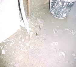
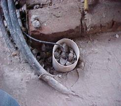
In relation to the place of installation of the electrodes (connecting rods) in the environment, it was seen that the majority of the work sites (88%) presented some not conformity for it is not recommendable that the connecting rods of grounding in humid areas and the neighborhoods of traffic or permanence of people or equipment are placed. The norm still demands that there mustn’t have presence of people, equipment or any other objects in a ray of at least 1m considering the coverage area of the step tension, however, 85% of the visited work sites did not take care of this requirement. Evidenced imperfections on the nailing of theelectrodes in 90% of the groundings was also displayed, there was no protection (box of inspection) against mechanical impacts or aggressive agents that can come to damage the same ones. Moreover in 57% of the workmanships there wasn’t an adjusted accessibility to be carried through periodic maintenances in the same, generating premature wear and tear of the elements of the grounding system (see table 4 and figure 2).
Results Agree%
Disagree
Localization of the grounding electrodes 12 88
Accessibility of the electrodes 85 15
Inspection box 10 90
Conservation state of the grounding elements
Source: Field research43 57
Table 4 –Localization of the grounding rods
 |
|
a) b) |
Figure 2 – Humid site grounding (a) and electrode with inspection box (b)
Analyzing more at great length the data a correlation is perceived between the transport of the construction companies and the fulfillment of the referring norms of installation of the groundings, where 20% of the great companies took care of the norms as for the place of grounding installation, while that 6.25% of the small constructors did not take care of norms that are related to this item, installing the grounding in humid places and/or the proximity of the traffic of people. These numbers, however, are on this side of what is expected to find exactly in the considered companies of great transport and demonstrates that the great majority of the enterprises possesses the equipment filled with earth with the elements (electrodes, connections and conductors) adjusted but they display imperfections in other important items of the norm many times due to knowledge or efficient fiscalization.
CONCLUSIONS
The study of the raised data demonstrated that the systems of equi- potentialization of the provisory electric installations of the work sites still present significant shunting lines in relation to the fulfillment of the lapsing established for norms NBR 5410 and NR 10, what demonstrates the necessity of consequently increasing the knowledge in relation to the systems of protection of the electrical installations, in order to manage them in efficient way taking the reduction in the number of accidents and diminishing the costs direct and indirect and with thesame ones, increasing the productivity at the work sites. Therefore, it is recommendable to program educative campaigns and/or actions, to prevent that the work sites beyond adequate material have access to the correct information as it uses them. These campaigns can reverse these indices found in the research, with spreading of the norms, and mainly the part related to the protection against electric shocks, besides informing and enabling the workers of the civil construction, in relation to the procedures of assembly, operation and maintenance of the provisory electric installations of the work sites. It must therefore be evidenced, as much for the public in general, as for the entrepreneurs of the industry of the civil construction, the importance of the use, adequate sizing and installation of the equi-potentialization systems so that they guarantee its effectiveness in the prevention of when requested the electric shocks.
ACKNOWLEDGMENTS
The authors would like to thank the FINEP, UPE, POLISHED, CELPE, HABITARE, SEBRAE and SINDUSCON/PE and the Laboratory of security and Hygiene of Work - LSHT of the Polytechnical School of the University of Pernambuco for the support in the accomplishment of this research.
REFERENCES
- 1. Cadick, John; CapelliSchellpfeffer, Mary e Neitzel, Dennis. Electrical Safety Handbook. Editora McGrawHill, EUA, 2000.
- 2. Alencar, L.H.; Procoro,A.C.; Villarouco, V.; Barkokébas Junior, B. Maior segurança nas instalações elétricas dos canteiros de obras: o uso do dispositivo de proteção à corrente diferencial residual em instalações temporárias. In: Congresso Brasileiro de Ergonomia, 13., 2005. Anais. Cd rom, 2005.
- 3. Barkokébas Junior, B. et al. A vida por um fio: instalações elétricas mais seguras em canteiros de obras. Revista Cipa NorteNordeste. Brasil, n.2, Janeiro de 2004.
- 4. Brasil, Ministério do Trabalho e Emprego. Normas Regulamentadoras de Segurança e Medicina do Trabalho. NR 10 Segurança em instalações e Serviços em Eletricidade. Disponível em: <http://www.mte.gov.br>. Acesso em: 6 ago. 2006.
- 5. ABNT Associação Brasileira de Normas Técnicas. NBR 5410: Instalações Elétricas de Baixa Tensão. Rio de Janeiro, 2004.
- 6. Mamede, João F. Instalações Elétricas Industriais. Rio de Janeiro : Editora LTC – Livros Técnicos e Científicos S.A, 6ª edição, 2002.
- 7. Creder, Hélio. Instalações elétricas, 11ª ed. Rio de Janeiro: Editora LTC, 1991.Livros Técnicos e Científicos S.A, 6ª edição, 2002.
- 8. Souza, J.R.A . Os Componentes da Instalação e a Proteção Contra Choques. Revista Eletricidade Moderna, nº181, abril/1989.
- 9. Caminha, Amadeu. Proteção de sistemas elétricos, 5ª ed. São Paulo: 2000.
Papers relacionados