


Introduction
The exposition to extreme temperatures can be considered something common among workers of different professional sectors, including firefighters. These expositions can be the cause of important injuries that can be reduced with the use of appropriate material combinations and effective designs in the manufacturing of protective equipment, such as safety footwear. Foot-related issues were identified by Gallanter and Bozeman [1] as one of the most frequent reasons for requiring medical attention, only after “preventive/hygiene and environmental”, in their study about illnesses and injuries at a major fire disaster.
Obtaining an optimal combination of ergonomic aspects and thermal insulation is not a simple question in different kinds of personal protective equipment, especially when the ambient conditions can be aggressive. To help in this process, the use of manikins has been considered advantageous by previous researchers, related to the heat transference through protective clothing, since very different points of view [e.g.: 2, 3, 4, 5, 6].
Previous studies have paid attention to the personal protective equipment (PPE) used by firefighters. For example, Taylor et al. [7] considered the physiological burden of the PPE commonly worn by firemen, concluding that “the footwear exerted the greatest relative metabolic load during walking”. The weight and sole flexibility of protective boots was considered by Chiou et al. [8] to evaluate their effects on firefighters’ spatiotemporal gait and physiological responses, providing valuable data for selecting and designing boots in order to reduce falls and overexertion. Other studies described the development of protective firefighter equipment, e.g. incorporating chemical and biological (CB) protection [9].
An important part of safety footwear, that must always be taken into account is the insole, as reflected in related standards [10, 11, 12] that specify the requirements for these PPE, including mechanical and thermal risks or ergonomic behaviour, among others, while special risks are covered by other specific standards, e.g. footwear for firefighters [13, 14]. Apart from the insole, according to the previous standards, the outsole must comply with the required restrictions in order to be marked as HRO (Heat Resistant Outsole). As explained in the following section, the boot used for the experiments of this study was made of fire-resistant nitrile rubber.
The use of insoles is very common in different sectors in order to improve comfort or related to musculoskeletal disorders. Previous researchers reflect its application in workers of different sectors, such as nurses [15], assembly workers [16], long-distance walking postmen [17], semiconductor industry employees [18], store and restaurant staff [19] or in the metal industry [20], among others.
Taking into account the high-temperature insulation requirements in the case of firefighters, more research could be useful in order to improve it, also taking into account comfort and ergonomic aspects. The main objective of this research was to develop the prototype of a system to test different combinations of protective and insulating materials in order to improve the thermal conditions on workers’ feet, particularly when they are exposed to high temperatures, considering several critical places on the bottom of foot and trying to reproduce a real environment.
As a consequence of the described objective, the obtained system was applied, under the methodology explained below, to real protective equipment. A real firefighter boot was exposed to previously specified conditions, in order to check how different insole combinations could affect to the time required to increase the temperature in the bottom of foot.
Prototype development process
The different parts of the prototype were developed according to the process explained in this section, combining different manufacturing techniques, to make possible the simulation of bones and tissues, allowing the placement of sensors on its bottom surface, to track the temperature values of three different points inside a shoe.
Foot development
The bones of the foot were reproduced with a high quality 3D printed piece, made of composite materials. The first stage of this process consisted of printing the digital model of the bones, extracting the unnecessary dust (Fig. 1a) and correctly cleaning all the obtained pieces with pressured air (Fig. 1b).

Figs. 1a-1b. Extracting unnecessary dust and cleaning de 3D-printed pieces with air.
All the pieces were made with a ZPrinter® 650 [21] and, for the finishing of the bones model, it was submerged in liquid hardener and dried during 24 hours. The obtained bones are shown below (Fig. 2), before placing the electronic components and covering them.

Fig. 2. 3D-printed bones before wiring and applying the polydimethylsiloxane.
The manufactured foot was 25.4 cm long (size 41, according to European standards [22]) and the required mould was based on a real foot. The mould was made covering a human foot with wet textile plaster and its internal surface was treated after its hardening process for optimum mould removing. This plaster mould made possible to place all the bones inside it (Fig. 3), to be surrounded by simulated muscles and tissues, after closing it.
The surrounding tissues were replicated with translucent polydimethylsiloxane (PDMS) to simulate their real flexibility and giving them the expected final aspect.

Fig. 3. 3D-printed bones in the sectioned plaster mould.
Electronic sensors and data acquisition system
The electronic sensor installation and the data acquisition system was specifically designed, configured and programmed for this prototype, taking into account the specifications required for this research purposes. One of the requirements was to monitor the temperatures in several points during relatively long periods and to be able to study their evolution, so they could be compared in order to observe advantages of different PPE designs and used materials. For this purpose, data were collected by means of a laptop computer (Toshiba Portege Z935, running Windows 8) and the sensored foot was connected to it through a USB interface.
To monitor several points of the bottom of foot, precision centigrade temperature sensors were used (Texas Instruments LM35). These electronic components are precision integrated-circuit temperature sensors, calibrated in ° Celsius, with 0.5°C ensured accuracy at +25°C, rated to operate over a -55°C to +150°C temperature range, being rated for a −40°C to +110°C range, according to the manufacturer’s specifications [23].
The electronic board used was based on a high-performance microcontroller (Atmel ATmega328) with 32KB flash memory with read-while-write capabilities, 1KB EEPROM and 2KB SRAM. This microcontroller has 23 general purpose I/O lines and 32 general purpose working registers [24], making possible to reach the initial objectives and also to increase the possibilities in future versions of the developed prototype.
The controlling software was developed to make one capture per second of all temperatures (three sensors were placed on the bottom of foot plus an additional sensor to monitor variations on the boot outsole). An ambient thermometer was added to the circuit in order to control the laboratory temperature during the experiments.
As the foot sensors were connected to the control board using cables that were covered by liquid during the manufacturing process, all the connections were carefully soldered and protected with heat-shrinkable rubber tubes (Fig. 4a).
In order to register the temperature dissimilarities on different places of the bottom of foot, three sensors were placed as reflected below (Fig. 4b). The applied criteria were related to the thickness of insulating material between the floor and the foot (due to the foot and outsole shapes).
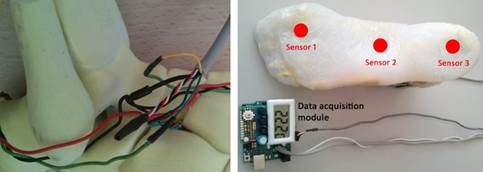
Figs. 4a-4b. Soldered connections (left) and position of the sensors (right).
The foot was covered with a real sock (composition: 64% cotton, 33% polyamide and 3% elastane) before being placed inside, avoiding the direct contact of the foot surface with the insole and the boot, trying to simulate a normal use of those elements. During all the tests, the sock was maintained dry (further research could include wet conditions) and the air exchange was avoided, as explained in the following section.
As one of the used insoles was customized to perfectly adapt to the sensored foot, its bottom surface was three-dimensionally scanned before manufacturing it. This process was made by an expert podiatrist (A. P.) in one of the Podoactiva S.L. clinics, using a 3D scanner with elastic membrane system (Figs. 6a-6b). This process is not detailed in this article because it was already described in the ORP 2012 Proceedings [20]. With the scanned model of the foot, a customized insole was manufactured milling a block of high-density polyethylene (HDPE) and covered by a piece of polyurethane (PU) with a thickness of 3 mm.

Fig. 6a-6b. 3D scanning process with elastic membrane system.
Boot, heating surface and thermal camera
Although the previously described elements could be used to asses any combination of shoe, insole and sock, this research was useful to test the developed system using real firefighting equipment on a controlled heating surface.
The boot model (Fal Fire) was selected according to the technical advice of experienced firefighters. A critical aspect for this selection was the appropriate outsole choice. This part of the boot was made of fire-resistant nitrile rubber, resistant to oil and hydrocarbons, to ensure compliance with the standards mentioned on the introduction of this article (marked as HRO, being resistant to contact with hot surfaces up to 300 °C). The boot was made of leather, with water repellent treatment, and a breathable Gore-Tex 4-layer membrane liner. Its original insole was made of non-woven synthetic fabric (Cambrelle) and polyester. An anti-perforation sole, made of steel, and a safety toecap, covered with a rubber protection, were also parts of the boot.
The heating surface was made of steel, electrically powered (radiant heat without flame), and its temperature was electronically controlled, being the same for all the tests, as described below. In addition to this electronic temperature control, a thermal imaging camera (Dräger UCF 9000) was used, as shown in Fig. 7.

Fig. 7. Boot on the heating surface.
Experimental method
To minimize the bias, all the tests were conducted by the same researcher, in the same laboratory and under homogenous conditions. The ambient temperature in all the tests was (25 ± 0.5) °C and the temperature of the heating surface was set at (145 ± 5) °C and continuously monitored with an analogic sensor, being confirmed with a thermal imaging camera (Fig. 7).
All the tests started with the foot and the boot at the ambient temperature. To start each test, the foot was introduced into the boot, with the insole that was being studied in each case correctly placed inside, as shown in Fig. 9. After introducing the foot, the cable was correctly placed and the boot was sealed, after being filled with an adaptable piece of low density polyethylene (LDPE), with an estimated density of 0.915 - 0.930 g/cm3 [25], which can withstand temperatures of 80°C continuously.

Fig. 8. Insoles tested (polyethylene-polyurethane, up; fabric-polyester, down).
Under the previously described conditions, four cases were studied in this research stage:
Test 1. No insole: although this option is not based on a real use possibility (according to the standards [13, 14] the original insole must be used as part of the boot), it was considered interesting, as part of this research, to identify the influence of insoles on the obtained results.
Test 2. Fabric-polyester insole (Fig. 8, down): as an original part of the boot, this test represents a normal use of the boot, conceived as a PPE.
Test 3. Polyethylene-polyurethane insole (Fig. 8, up): the original one was removed and replaced by a customized insole.
Test 4. Both insoles: the polyethylene-polyurethane insole was placed on the original one, so the effect of both was observed.

Fig. 9. Sensored foot with sock and insole illustratively placed in a sectioned boot.
Results
Although all the tests started with the foot at ambient temperature, only the 30 to 40 °C interval was considered relevant for this study, taking into account the typical foot temperature variation as the starting point [26].
The temperature values (°C) of each sensor were captured by means of the developed system and stored as a comma-separated values (CSV) file for each test. Those files were imported to the statistical software Stata v. 12 for the data analysis of each test. With it, an independent twoway graph was created for each test, in order to plot a median-band line for each sensor of the foot, so they were graphically comparable, as shown below (Fig. 10).
|
Test 1. No insole: 1573 seconds. |
Test 2. Fabric-polyester insole: 1805 seconds. |
|
Test 3. Polyethylene-polyurethane insole: 2282 seconds. |
Test 4. Both insoles: 2429 seconds. |


Fig. 10. Evolution of the temperatures during the 30 to 40 °C interval.
These results showed that there are clear differences among the temperature registered by each sensor, particularly at the end of the tests. It can be noticed that sensor 1 registered higher temperatures compared with sensor 3 (Fig. 10) and this difference was clearly greater comparing measurements from sensors 1 and 2. Paying attention to the last values of each series, Table 1 summarizes the temperatures registered by each sensor at the end of the four tests.
|
Sensor 1 |
Sensor 2 |
Sensor 3 |
|
|
Test 1 |
40.0 |
31.3 |
36.6 |
|
Test 2 |
40.0 |
31.3 |
36.1 |
|
Test 3 |
40.0 |
32.7 |
37.0 |
|
Test 4 |
40.0 |
33.2 |
36.2 |
Table 1. Temperature on each sensor at the end of the tests.
The graphs also revealed that, while the plotted lines had clear similarities in the four tests, the slopes varied among the different sensors and the times for the 30 to 40 °C intervals were clearly different: from 1573 seconds in Test 1 to 2429 seconds in Test 4. The time variations for the four tests have been graphically summarized in Fig. 11.

Fig. 11. Comparison of the 30 to 40 °C intervals of the four tests.
Discussion
According to the graphs in Fig. 10, the differences among the temperatures of each sensor would have clear consequences in the maximum exposure times of different points of the bottom of foot. Sensor 1 registered slightly augmented temperatures compared to sensor 3 (differences from 3.0 °C in Test 3 to 3.9 °C in Test 2), but those temperature increments were around double considering sensors 1 and 2 (from 6.8 °C in Test 4 to 8.7 °C in Tests 1 and 2). According to the previous data, sensors 1 and 2 had a mean difference of 7.9 °C, at the end of the four tests, while that difference was 3.5 °C comparing sensors 1 and 3.
The different insole combinations had also different time results in the 30 to 40 °C intervals. The variation between the boot without its original insole (1573 s or 26.2 minutes) and with it (1805 s or 30.1 minutes) means an increment of less than 4 minutes, which represents a 14.7%. In contrast, if the original insole is replaced by the customized insole, used in the 2nd test (2282 s or 38.0 minutes), there is a new increment of 11.8 minutes or a 45.1%. This means that an improved insole could increase around three times the studied time increment.
Conclusions
The clearly different results that were obtained by each sensor make possible to conclude that temperature can not only be measured in one point or, at least, the worst case should be previously known in order to correctly place a single sensor. In the studied case, it is clear that the hottest point is in the front (sensor 1), where the thickness of both, outsole and insole, was thinner, so the temperature increasing resulted much faster.
The application of the developed system can effectively help to improve equipment conceived to protect workers under extreme thermal conditions, e.g. firefighters walking on hot surfaces, and to assess materials or equipment, comparing their insulating properties. Thus, this sensored foot can be considered a useful instrument to assess firefighting equipment and a complementary tool to other methods to calculate clothing insulation [27] and safety standards’ requirements during the design and testing stages of safety footwear.
According to results, the boot outsole, made of nitrile rubber, worked very well as an insulating piece and the customized insole made of polyethylene and polyurethane (Test 3) obtained the greatest time increment (45.1%), so these materials could be more appropriate in cases of workers exposed to extreme temperatures. Although placing both insoles gave better results (Test 4 vs. Test 3), the increment was only 2.4 minutes, which means an improvement of just a 6.4%.
Apart from other considerations related to comfort or prevention of work-related musculoskeletal disorders [e.g.: 15, 16, 17, 18, 19, 20], the use of the correct insoles can increase the thermal insulation, being an important part of personal protective equipment.
Further research
As the developed system makes possible to capture temperatures on the bottom of foot and analyze the obtained data, it can be applied to very different purposes in future research. Although it was firstly applied to high temperatures, it could also be useful to test the opposite: footwear in extremely cold environments.
Many different combinations of socks, insoles and safety boots could be tested in the future, paying special attention to the features of different materials to improve personal protective equipment. This could be useful from the point of view of PPE manufacturers and also for preventive services, trying to compare different aspects related to occupational safety and ergonomics.
Finally, it could also be useful to study different variations of the settings in the experiments, in order to compare several simulated condition. For example, this research only considered dry socks, but the simulation of moisture caused by real foot perspiration might also be taken into account.
Acknowledgements
The researchers would like to thank Podoactiva S.L. for the podiatric advice and the manufacturing of the customized insole used in this study. Our thanks go also to the Integrated College of Technical Training “Corona de Aragón” from Zaragoza (Spain) for making possible the use of the ZPrinter® 650, which was available as part of a project funded by the Spanish Government under Grant ‘BOE-A-2011-16800- P.111866’ [28]. Finally, our appreciation is also extended to the managers of the Fire Protection Service of the Diputación Provincial de Zaragoza, for the technical information on firefighting methods and materials.
References
- 1. Gallanter T, Bozeman WP. Firefighter illnesses and injuries at a major fire disaster. Prehospital Emergency Care: official journal of the National Association of EMS Physicians and the National Association of State EMS Directors. 2002; 6 (1): 226.
- 2. Broede P, Candas V, Kuklane K, den Hartog E, Havenith G, THERMPROTECT network. Effects of heat radiation on the heat exchange with protective clothing a thermal manikin study. Proceedings of 3rd European Conference on Protective Clothing (ECPC), Poland, May 2006, Central Institute for Labour Protection National Research Institute.
- 3. Oliveira AVM, Gaspar AR, Quintela DA. Measurements of clothing insulation with a thermal manikin operating under the thermal comfort regulation mode: comparative analysis of the calculation methods. European Journal of Applied Physiology. 2008; 104 (4): 679688.
- 4. Brode P, Kuklane K, Candas V, den Hartog EA, Emiel A, Griefahn B, Holmer I, Meinander H, Nocker W, Richards M, Havenith G. Heat Gain From Thermal Radiation Through Protective Clothing With Different Insulation, Reflectivity and Vapour Permeability. International Journal of Occupational Safety And Ergonomics. 2010; 16 (2): 231244.
- 5. Den Hartog EA, Havenith G. Analytical Study of the Heat Loss Attenuation by Clothing on Thermal Manikins Under Radiative Heat Loads. International Journal of Occupational Safety and Ergonomics. 2010; 16 (2): 245261.
- 6. Foda E, Siren K. A thermal manikin with human thermoregulatory control: Implementation and validation. International Journal of Biometeorology. 2012; 56 (5): 959971.
- 7. Taylor NAS, Lewis MC, Notley SR, Peoples GE. A fractionation of the physiological burden of the personal protective equipment worn by firefighters. European Journal of Applied Physiology. 2012; 112 (8): 29132921.
- 8. Chiou SS, Turner N, Zwiener J, Weaver DL, Haskell WE. Effect of boot weight and sole flexibility on gait and physiological responses of firefighters in stepping over obstacles. Human Factors. 2012; 54 (3): 373386.
- 9. Barker R, Deaton S, Liston G, Thompson D. A CB Protective Firefighter Turnout Suit. International Journal of Occupational Safety and Ergonomics. 2010; 16 (2): 135152.
- 10. International Organization for Standardization (ISO). Personal protective equipment Safety footwear (Standard No. ISO 20345:2011).
- 11. European Committee for Standardization (CEN). Personal protective equipment. Safety footwear (Standard No. EN ISO 20345:2011). Brussels, Belgium: CEN; 2011.
- 12. Spanish Association for Standardisation and Certification (AENOR). Equipo de protección individual. Calzado de seguridad. UNEEN ISO 20345:2012. Madrid, Spain, AENOR; 2012.
- 13. European Committee for Standardization (CEN). Footwear for firefighters. (Standard No. EN 15090:2012). Brussels, Belgium: CEN; 2012.
- 14. Spanish Association for Standardisation and Certification (AENOR). Calzado para bomberos. UNEEN 15090:2012. Madrid, Spain, AENOR; 2012.
- 15. Chiu MC, Wang MJ. Professional footwear evaluation for clinical nurses. Applied Ergonomics. 2007; 38 (2): 133141.
- 16. Almeida JS, Carvalho Filho G, Pastre CM, Padovani CR, Martins RADM. Comparison of plantar pressure and musculoskeletal symptoms with the use of custom and prefabricated insoles in the work environment. Revista Brasileira de Fisioterapia. 2009; 13 (6): 542548.
- 17. Shabat S, Gefen T, Nyska M, Folman Y, Gepstein R. The effect of insoles on the incidence and severity of low back pain among workers whose job involves longdistance walking. European Spine Journal. 2005; 14 (6): 546550.
- 18. Lin CL, Wang MJ, Drury CG. Biomechanical, physiological and psychophysical evaluations of clean room boots. Ergonomics. 2007; 50 (4): 481496.
- 19. Messing K, Kilbom A. Standing and very slow walking: foot painpressure threshold, subjective pain experience and work activity. Applied Ergonomics. 2001; 32 (1): 8190.
- 20. GarcíaHernández C, MarínZurdo J, HuertasTalón JL. Ortosis plantares personalizadas para la mejora de los síntomas generados por patologías en trabajadores de la industria del metal. ORP Conference 2012.
- 21. 3D Systems. ZPrinter® 650 Features and Specifications available online on the website: http://www.zcorp.com/en/Products/3DPrinters/ZPrinter650/spage.aspx (last access: 22nd November 2013).
- 22. European Committee for Standardization (CEN). Size designation of clothes Part 3: Body measurements and intervals. (Standard No. EN 134023:2013). Brussels, Belgium: CEN; 2013.
- 23. Texas Instruments. LM35 Precision Centigrade Temperature Sensors Datasheet is available online on the website: http://www.ti.com/lit/ds/symlink/lm35.pdf (last access: 22nd February 2014).
- 24. Atmel Corporation. ATmega328 Microcontroller datasheet is available online on the website: http://www.atmel.com/devices/atmega328.aspx (last access: 22nd February 2014).
- 25. Malpass DB. Single Site Catalysts, in Introduction to Industrial Polyethylene: Properties, Catalysts, and Processes. 2010; John Wiley & Sons, Inc., Hoboken, NJ, USA.
- 26. Nardin RA, Fogerson PM, Nie R, Rutkove SB. Foot Temperature in Healthy Individuals: Effects of Ambient Temperature and Age. Journal of the American Podiatric Medical Association. 2010; 100 (4): 258264.
- 27. Kuklane K, Gao CS, Holmer I, Giedraityte L, Brode P, Candas V, den Hartog E, Meinander H, Richards M, Havenith G, Thermoprotect Study Grp. Calculation of clothing insulation by serial and parallel methods: Effects on clothing choice by IREQ and thermal responses in the cold. International Journal of Occupational Safety and Ergonomics. 2007; 13 (2): 103116.
- 28. Spain, 2011. BOE Num. 258 of 26 Oct. 2011. Sec. III. Page. 111871. Online version available at: https://www.boe.es/boe/dias/2011/10/26/pdfs/BOEA201116800.pdf (last access: 14th March 2013).
Papers relacionados